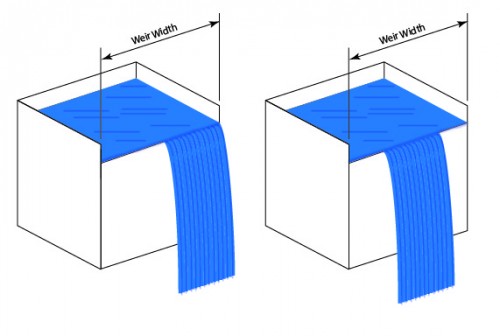
The concept and purposes of an overflow weir are pretty simple but making them perform for maximum benefit can be a challenge. For the best performance of a weir used in a skimming application, liquid should overflow the entire width of the weir. An area of stagnation is formed behind an area where there is no overflow. There are a several factors that can affect the nature of flow over a weir – –
- Weir Width
- Liquid Flow Rate
- Weir Geometry
- Level of the Weir
- Liquid Properties
The first two, weir width and flow rate, go hand-in-hand. In the case of a relatively narrow weir, a few inches for example, it doesn’t take much flow to achieve flow over the entire width of the weir. As the width of the weir is increased, however, achieving full width flow requires a higher and higher flow rate to overcome the forces of surface tension of the liquid which favor the flow being confined to as narrow a stream as possible.
Note – This is especially true if the liquid is de-ionized water (which has very high surface tension).
Although there are instances where a “perfect” weir won’t overflow its entire width due to surface tension, it’s worth checking to assure that non-uniform flow is not due to the weir geometry and/or the fact that it is not level.

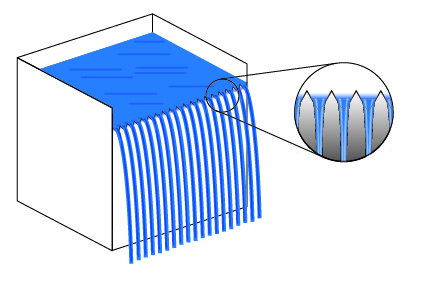
One way to help assure that liquid flows over the entire width of a weir is to increase flow. When increasing flow is not an option, other measures may be required to achieve the desired effect. One of the more common options is the saw-tooth weir as shown below.

In effect, the saw-tooth design reduces the width of the overflow weir thereby reducing the flow required to achieve full width flow. In addition, because of the increased flow velocity through each “V” of the sawtooth, leveling of the tank (or the more difficult case of a machine with several tanks) becomes less critical. This design is particularly beneficial in the case of a four-sided overflow weir in which liquid overflows all four edges of a tank. The four-sided overflow increases the width of the weir to the length of all four sides of the tank unless the saw-tooth design is utilized. Since many four-sided overflow weirs are in rinse tanks with single pass de-ionized water, a lower flow is a desirable.
The one possible “down-side” to the sawtooth weir is that there can’t help but be a small area of liquid stagnation behind each one of the projecting “teeth.” Care should be taken to avoid withdrawal of parts through these stagnant zones which might result in re-deposition of contaminants trapped in the stagnant zones.
– FJF –

 Water – De-ionized – Hints
  A Fond Farewell to John Fuchs
  Millipore Testing – Evaluation by Particle Counting
  Tape Test for Cleaning Revisited